TL;DR
- You can replace the Tuya WB3S with an Espressif ESP-12F (or ESP-12E) and ESPHome.
- You need to pull EN up to 3.3v, and pull GPIO15 down to ground via a 10k resistor.
- If you’re on Linux, make sure your user is in the
dialoutgroup to write to the ESP-12. - Scroll to the end for the YAML.
- Comment out the appropriate buttons for your model.
- I’ve confirmed that SSW01G-WIFI uses button 2, and SSW02G-WIFI uses buttons 1 and 3. Presumably SSW03G-WIFI uses all of them, but I don’t have one to confirm.
- Make sure you change
light.toggleintofan.toggleif you decide to declare a button as a fan, etc.
The article
The Mercator Ikuü range of smart devices is another rebranded Tuya line. As a result, controlling the device with Home Assistant was slow due to the calls to the Tuya datacentre - and honestly I just wanted to have devices that are entirely under my control. I started by disassembling the switch and immediately saw the Tuya WB3S on the underside of the top plate.
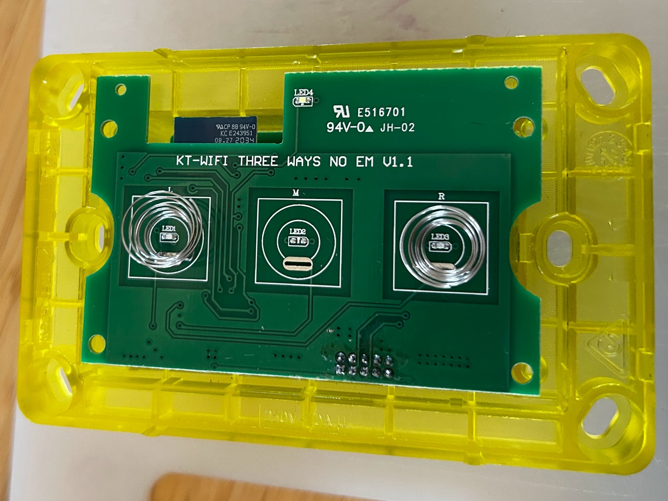
The switch, opened up. The controlling PCB sits on the underside of the top plate.
Be careful lifting this PCB out, as there are pins connecting it to the 240v plane - make sure you lift it straight. This set of connecting pins is labelled CN1, and is responsible for connecting the controlling MCU to the 240v relays.
On the board is the Tuya WB3S, and a Holtek BS813A-1 touch-button sensor (https://www.holtek.com.tw/page/vg/BS81xA-x). It does not appear to contain a TuyaMCU chip. Judging by the silkscreen and component placements, the same pcb is used for the SSW01G-WIFI, SSW02G-WIFI, and SSW03G-WIFI models.
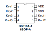
The Holtek BS813A-1 touch sensor pinout.
The way this Holtek sensor works (which I discovered later in the blog by dumping the firmware): while a touch is sensed by the Key1 leg, it will pull Kout1 down to zero volts. This is momentary and returns to 3.3v once the touch is removed. The microchip listens for the appropriate pin to be pulled low, and triggers a relay in response.
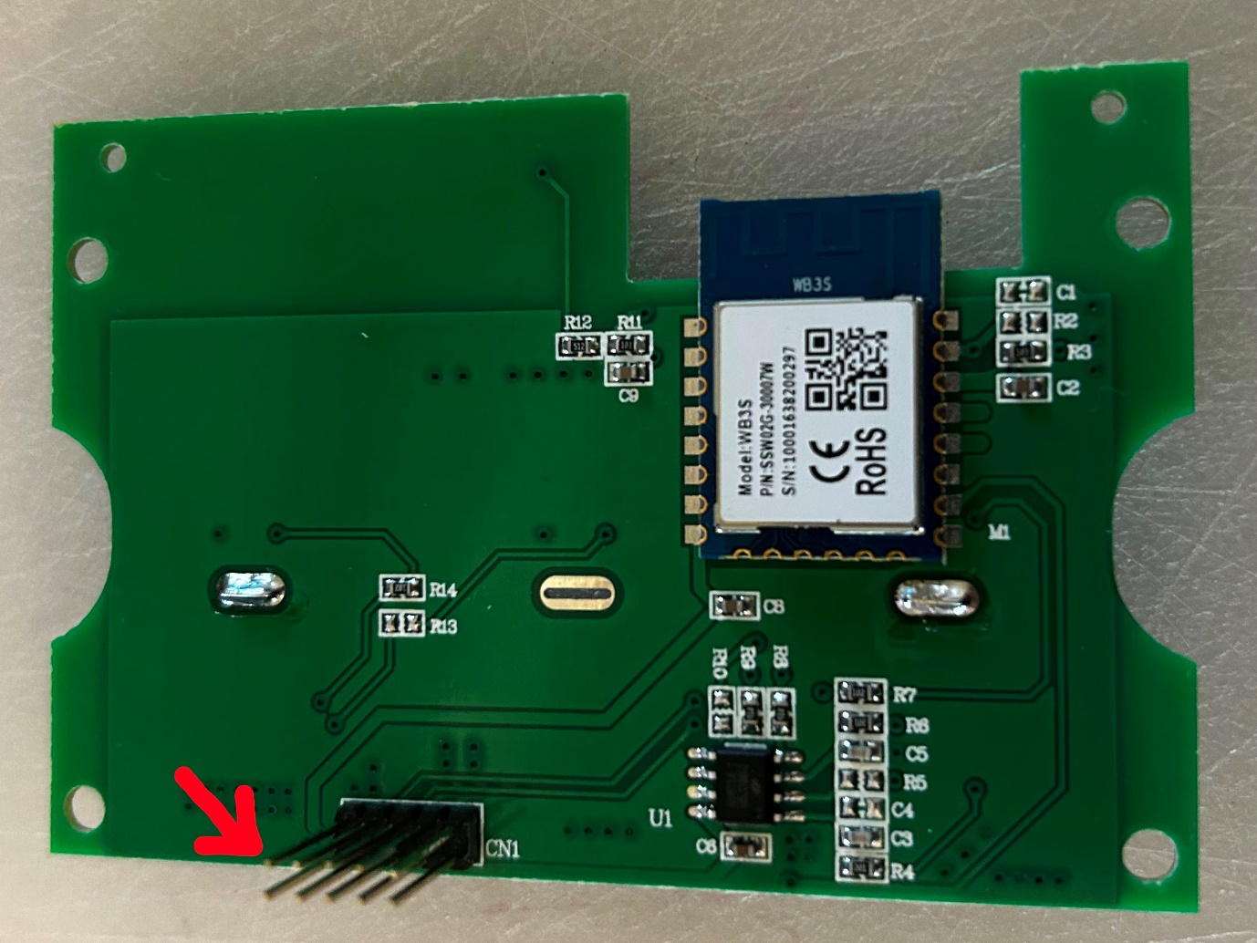
The controller board. The red arrow marks where I (incorrectly) oriented my CN1 numbering from.
The red arrow is where I oriented my CN1 pin naming from. I’ll refer to the CN1 pins in reading order; pins 1-5 on the top row, pins 6-10 on the bottom. After writing this, I realised that this is almost certainly backwards: the bottom-right pin — what I call pin 10 — has a square base, indicating it should have been pin 1. Oh well.
Here’s the pinout of the Tuya WB3S, from https://docs.libretiny.eu/boards/wb3s/:
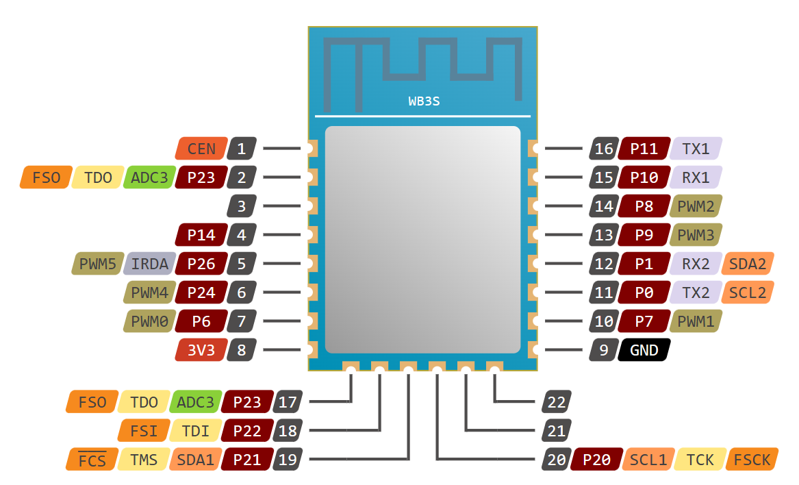
The Tuya WB3S pinout, via LibreTiny.
Note, the grey numbers in the WB3S pinout are simply positions; the pin names are burgundy (i.e., P23 is in position 2). I can see PCB traces at positions 15, 14, 13, 12, 10, 9 (GND), and 8 (3.3v). Positions 17-22 are visibly unsoldered.
- WB3S GND (position 9) goes to CN1 Pins 1 & 2
- WB3S 3.3v (position 8) goes to CN1 Pin 6
- WB3S P6 (position 7) goes to CN1 Pin 7, via resistor R7, and on to LED1
- WB3S P7 (position 10) goes to CN1 pin 9, via resistor R14, and on to LED3
- WB3S P8 (position 14) goes to capacitor C2 and onto CN1 pins 1 & 2
- WB3S P9 (position 13) goes to CN1 pin 8, via resistor R13 and LED2 (empty on this model)
- WB3S P10 (position 15) goes to resistor R2, which is empty on this model
- WB3S P24 (position 6) goes to resistor R11, which goes on to LED4 (plate lighting)
And the inverse to cross-check myself: on CN1, I can see upper PCB traces at 1, 2, 6, 7 and 8 - plus an underside trace to 9.
- CN1 Pin 1 goes to WB3S GND (position 9)
- CN1 Pin 2 goes to WB3S GND (position 9)
- CN1 Pin 6 goes to WB3S 3.3v (position 8)
- CN1 Pin 7 goes to WB3S P6 (position 7) via resistor R7, which then goes to LED1
- CN1 Pin 8 goes to WB3S P9 (position 13) - this also traces to R13, which is empty on this model, and appears to be for the absent middle switch LED2
- CN1 Pin 9 goes to WB3S P7 (position 10) via resistor R14, and onward to LED3
I double-checked this by powering up the WB3S chip and checking the voltage on the pins as I hit the buttons. All seems correct so far. Before I desoldered the WB3S from the pcb, I connected RX and TX and dumped the Tuya firmware, and decoded this with the OpenBeken flash tool from https://github.com/openshwprojects/BK7231GUIFlashTool. Here are the interpreted results:
Device configuration, as extracted from Tuya:
- Button (channel 1) on P24 [pinout position 6]
- Relay  (channel 2) on P7  [pinout position 10]
- Button (channel 2) on P8  [pinout position 14]
- Relay  (channel 1) on P6  [pinout position 7]

Device seems to be using WB3S module, which is using BK7231T.
And the Tuya section starts, as usual, at 2023424
These results didn’t align with my original tracing, so it was really lucky I did this. Although I had correctly identified the relays in position 7 & 10, I had misunderstood how the buttons work. It was thanks to this discrepancy that I started testing the levels while touching the touch sensors, and discovered that button-presses cause the voltage to drop on P8 (position 14) and P24 (position 6). This led me to read up on how the Holtek chip works, helping me to understand what’s going on here!
So, indeed we have two buttons and two relays. The buttons are held HIGH while untouched, and momentarily drop to LOW when touch is detected. In turn, these state changes trigger toggles to the relay outputs. I can finally start writing YAML!
I’m replacing this Tuya WB3S with an Espressif ESP12-F, which is a perfect drop-in replacement:
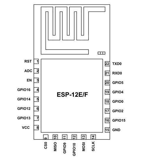
The ESP-12 pinout.
Translating from the WB3S, it appears:
- P24 (position 6 on the WB3S) maps to GPIO12 on the ESP12
- P7 (position 10 on the WB3S) maps to GPIO15 on the ESP12
- P8 (position 14 on the WB3S) maps to GPIO5 on the ESP12
- P6 (position 7 on the WB3S) maps to GPIO13 on the ESP12
- P10 (position 15 on the WB3S) maps to RX on the ESP12
- Additionally, EN needs to be pulled up to 3.3v, and GPIO15 needs to be pulled down to ground via a 10k resistor.
This is my first time programming an ESP12 (my previous ESPHome devices have been ESP32’s), and I did find them a little more difficult. Skill issue, I know.
I ended up bumping into a permissions problem, and thanks to this post I was able to resolve the error failed to execute 'open' on 'SerialPort': Failed to open serial port. The solution was either to add myself to the dialout group, or set the ACL on ttyUSB0 (only a transient workaround):
sudo setfacl -m u:USERNAME:rw /dev/ttyUSB0
sudo usermod -aG dialout USERNAME
Desoldering the original Tyua WB3S was enough of a challenge that I asked a friend for help, and he did the first couple for me while I waited for a hot plate to arrive from AliExpress. Then I did the third one and only slightly cooked my board.
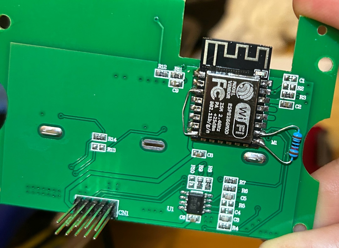
The ESP-12F in place, complete with the 10k pull-down bodge resistor.
Result! Not only is this 100% locally-controlled and forever disconnected from the Tuya Cloud, but the response time is ridiculously fast now. What used to be 200~2000ms response time (yes really, depending on network congestion), is now closer to 20ms (unmeasurably fast with my … [checks] … zero instruments).
The YAML snippet
Example YAML for the one-gang, two-gang, and/or three-gang versions is below. If you’re brand-new to ESPHome, note this is partial YAML and will need tweaking; other important parts such as enabling the API and OTA are left out.
esp8266:
  board: esp01_1m

binary_sensor:
  # Button 1 - not present on the SSW01G
  - platform: gpio
    id: button_1
    pin:
      number: GPIO12
      inverted: true
      mode: INPUT_PULLUP
    on_press:
      then:
        - light.toggle: switch_1
    internal: True

  # Button 2 - not present on the SSW02G
  - platform: gpio
    id: button_1
    pin:
      number: RX
      inverted: true
      mode: INPUT_PULLUP
    on_press:
      then:
        - light.toggle: switch_2
    internal: True

  # Button 3 - not present on the SSW01G
  - platform: gpio
    id: button_3
    pin:
      number: GPIO5
      inverted: true
      mode: INPUT_PULLUP
    on_press:
      then:
        - light.toggle: switch_3
    internal: True

output:
  # Relay 1 - not present on the SSW01G
  - platform: gpio
    id: relay_1
    pin: GPIO13

  # Relay 2 - not present on the SSW02G
  - platform: gpio
    id: relay_2
    pin: GPIO4

  # Relay 3 - not present on the SSW01G
  - platform: gpio
    id: relay_3
    pin: GPIO15

# Expose the relays as lights and/or fans
light:
  # Light 1 - not present on the SSW01G
  - platform: binary
    name: Switch 1
    output: relay_1
    id: switch_1

  # Light 2 - not present on the SSW02G
  - platform: binary
    name: Switch 2
    output: relay_2
    id: switch_2

  # Light 3 - not present on the SSW01G
  - platform: binary
    name: Switch 3
    output: relay_3
    id: switch_3

# Example of having a fan on button 3 instead - if you do this, you must change
# the earlier matching button declaration from light.toggle to fan.toggle.
fan:
  - platform: binary
    # Button 3
    name: Ensuite Fan
    output: relay_3
    id: switch_3
That’s it! Upload that fragment into your normal ESPHome setup, and you should be in business.